
Turned features
Diameters, lengths, shoulders and bores describe the round form. Each feature needs its specified dimensions, tolerances and reference relationships.
CNC plastic turning · Aurora, Illinois
CDS turns engineered plastics, aluminum, brass and bronze. Our twin-spindle, fully live-tooled setup can produce round parts with milled operations in one cycle, subject to the actual drawing and equipment fit.
Diameters, bores and shoulders
In CNC turning, the workpiece rotates while a tool removes material. Outer and inner diameters, faces, shoulders, grooves and bores are defined around the rotational axis.
A round plastic part may also need flats, cross-holes or other milled features. The drawing specifies their positions relative to the bore, shoulder or reference face.
Diameters, lengths, shoulders and bores describe the round form. Each feature needs its specified dimensions, tolerances and reference relationships.
Flats and cross-holes add angular and positional relationships to the turned form. They belong on the same controlled drawing.
CDS's twin-spindle, fully live-tooled setup combines turning and milled operations in one cycle for suitable parts. Part geometry and tool access determine the machining sequence for your drawing.
See custom rollers and machined bushings for component-specific drawing and quotation information.
People and equipment
CDS's lathe specialists have decades of experience. The department includes the twin-spindle, fully live-tooled capability for round parts with milled operations.
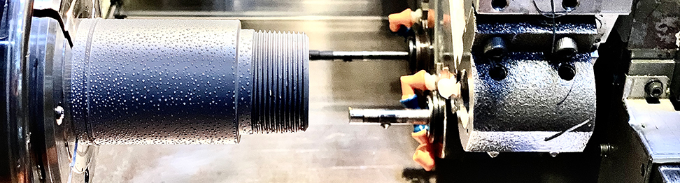
Part diameter, length and feature access need to fit the equipment and workholding. Confirm those requirements and availability for the actual project.
Material and dimensional relationships
Resin grade, stock condition, wall thickness and support can affect dimensional control. The customer drawing defines the dimensions and acceptance requirements.
Engineering plastics respond to heat, restraint and cutting forces differently from metals. The exact material and stock condition influence how a turned part behaves during machining and in service.
Thin or uneven walls, grooves and unsupported features can affect restraint and deflection. The inside and outside geometry need consideration together.
A bore can be the correct size and still have an unacceptable relationship to another feature. Datums, roundness, runout, cylindricity and positional requirements explain what acceptance depends on.
Tolerance feasibility is specific to the material, geometry and setup. Critical diameters, lengths and mating surfaces need buyer-defined acceptance requirements and an inspection method.
Threads, sealing surfaces and functional finish can be included as requirements for CDS to evaluate. A feature name alone does not confirm that every size or configuration can be machined.
The engineered-plastic material pages explain general material behavior. Provide the exact grade specified for your part, including any controlled brand, filler or permitted substitute.
Request a turning quote
Share the current drawing and revision, or the available specification, sketch, model or sample information. Identify whether the request is for a prototype, replacement or production quantity.